
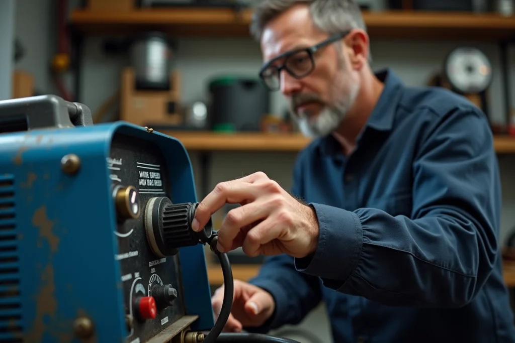
The 0.9 mm flux-cored wire delivered with Parkside machines (PFDS 33 B3, PMSG 200 A1, and variants) imposes adjustment constraints that solid wire under gas does not. The wire feed speed directly influences the stability of the arc and the amount of metal deposited, but on these simplified adjustment machines, the margin for error is slim. Here we detail the parameters that really matter and the specific pitfalls of Parkside flux-cored wire.
Rollers and flux-cored wire guidance: the often-overlooked prerequisite
The flux-cored wire is a hollow tube filled with flux. It deforms more easily than solid wire if the pressure from the drive rollers is too high. On Parkside machines, the pressure knob for the rollers does not have reliable graduations. We recommend tightening just enough so that the wire does not slip when pulling it by hand, without crushing the section.
A flux-cored wire crushed by overly tight rollers causes jams in the sheath, jerky feeding, and an unstable arc that resembles a speed issue when the cause is purely mechanical. Before adjusting the speed potentiometer, check this point.
To deepen the mechanical diagnosis and the specifics of the Parkside range, you can consult Parkside’s advice on Be At Home which details the startup steps.
- Use the smooth groove (without V-groove) if your machine is equipped with one, as the V-groove marks the flux-cored wire and weakens the sheath.
- Ensure that the contact tube matches the 0.9 mm diameter: a worn or oversized tube allows the wire to vibrate in the last centimeter, creating erratic micro-arcs.
- Manually unroll about one meter of wire before the first weld to spot any bends or twists in the spool.
Wire speed and amperage on Parkside machines: the relationship to understand
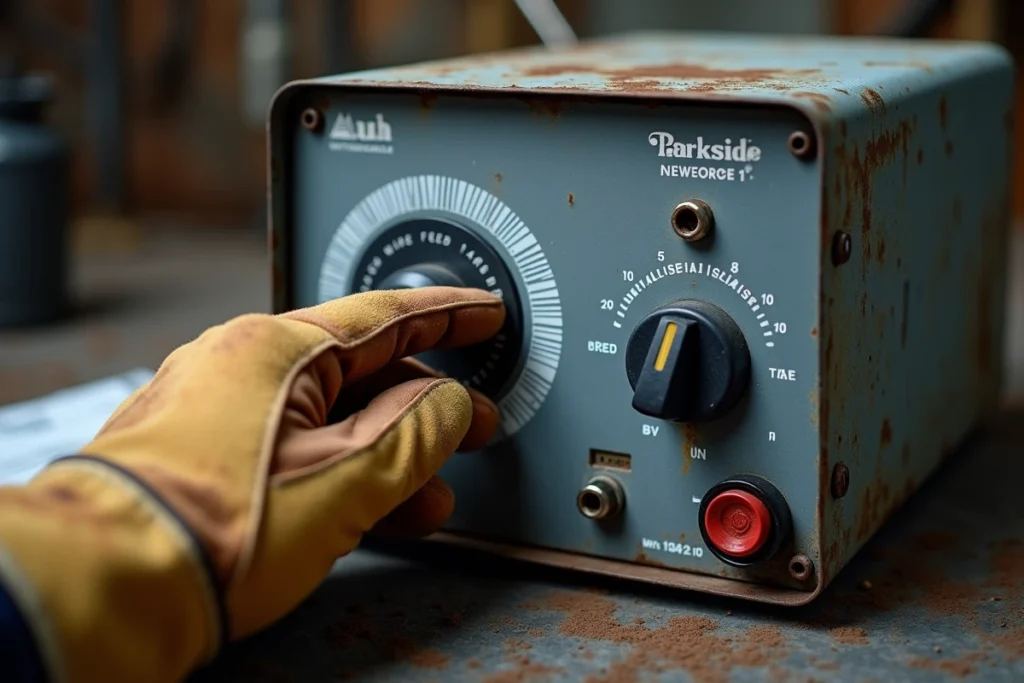
On most entry-level Parkside machines, the wire speed and amperage are linked by a single potentiometer. Turning the knob simultaneously increases both the intensity and the wire feed. Some models (PMSG 200 A1) separate the two settings, offering more latitude. First, identify your machine’s configuration before looking for values.
With a 0.9 mm flux-cored wire on 1.5 mm sheet metal, the most reliable field feedback places the amperage slider around the low mid-position and the wire feed speed slightly above halfway. On the PFDS 33 B3, a user reports a correct result at about 70 A with a feed between 5 and 6 on the machine’s scale, but with frequent burn-throughs if the torch stays in one spot too long.
Burn-through on thin sheet metal is the number one problem with Parkside flux-cored wire. It is not resolved solely by wire speed. The short stitch welding technique, with cooling between each stitch, limits the temperature rise much better than a continuous bead. On sheet metal of 1.5 mm or less, we systematically prefer this approach.
Interpreting the sound of the arc to adjust the speed
A stable MIG arc produces a regular crackle. If the sound is choppy with brief extinguishments, the wire speed is too high relative to the voltage: the wire plunges into the puddle without having time to melt. Conversely, a high-pitched sizzling with a lot of spatter indicates a speed that is too low, causing the arc to lengthen and become unstable.
On single-setting machines, make adjustments in quarter graduations on the potentiometer between two tests on a piece of the same thickness. Note each combination on a piece of cardboard taped to the machine: these machines do not have program memory.
Polarity and gasless flux-cored wire: the adjustment that many forget
Gasless self-shielded flux-cored wire requires negative polarity at the electrode (DCEN), meaning that the ground clamp is connected to the + and the torch to the -. Parkside machines delivered with flux-cored wire are generally factory-set to DCEN, but after changing the spool or switching to solid wire under gas, the polarity may have been reversed.
Reversed polarity in flux-cored wire generates a violent arc, massive spatter, and almost no penetration. The bead looks like a pile of droplets sitting on the sheet without melting. If you observe this behavior despite correct speed settings, open the connection compartment and check for cable inversion.
Parkside flux-cored wire and bodywork: the limits of the process
Gasless flux-cored wire remains a compromise for working without a bottle. On thin body panels (often less than one millimeter), even a perfect wire speed adjustment does not compensate for the higher heat input of FCAW compared to MIG/MAG under gas. The flux contained in the wire generates a slag that must be chipped off after each pass, and the finish is significantly rougher.
For body panels, switching to 0.6 mm solid wire under argon-CO₂ mix remains the standard. Parkside flux-cored wire is better suited for light metal assemblies, workbench frames, or repairs of mild steel structures starting from 1.5 mm thickness.

Welding environment and arc stability with flux-cored wire
Gasless flux-cored wire creates its own protective atmosphere thanks to the burning flux. However, this protection is sensitive to drafts. Outdoors or in an open workshop, a moderate draft disperses the protective gases from the flux and causes porosity in the bead.
The instinctive reaction is to increase the wire speed to “force” penetration. This is counterproductive: it increases spatter without correcting porosity. The right approach is to protect the welding area with a shield (plate, thick cardboard) and maintain the validated settings in the workshop.
Lastly, a point often overlooked: the original Parkside flux-cored wire is not always of consistent quality from one spool to another. If your usual settings no longer work after changing spools, test on a scrap piece before modifying the machine’s parameters. The actual wire diameter and flux composition vary enough between batches to shift the optimal operating point.